Time-of-Flight: Tackling 3D Challenges
Time-of-Flight: Tackling 3D Challenges |
So far in this series of 3D machine vision blogs we have introduced 3D machine vision and explored some of the main technologies used in machine vision (Stereo Vision, Time-of-Flight, Structured Light, and 3D Profiling/Laser Triangulation).
In this blog post we will cover Time-of-Flight (ToF), exploring the technology in play and how it can tackle 3D challenges in machine vision.
What is Time of Flight (ToF)?
The Time-of-Flight imaging technique allows 3D imaging without scanning an object. This approach relies on illuminating an object with a modulated light source. The position of the object is then determined by the travel time of a pulse-based light sent by the emitter and its return to the sensor after being reflected by an object, hence the name Time-of-Flight.
Revolutionised Time-of-Flight Sensors
Historically, Time-of-Flight has raised questions over its accuracy, and has generally been regarded as an inferior 3D technology with limited sensor technology only able to provide a poor degree of accuracy (1-2cm) with no payoff in frame rate.
However, Sony’s DepthSense ToF sensors have revolutionised the technology, able to provide accuracy to the nearest millimetre, which means no more guessing games for system integrators working with finer degrees of accuracy.
The IMX556 DepthSense ToF sensor features CAPD and backside-illuminated (BSI) technology – technologies that produce superior depth precision compared to existing ToF solutions on the market.

Sony IMX556 DepthSense Sensor
Time of Flight Camera Breakdown
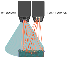
ToF 3D cameras comprise a lens, an integrated light source, a sensor that stores all capture image information, and an interface. Whilst all modern imaging systems will include sensors, lenses, interfaces, and often illumination modules, this approach is different; at the heart of a Time-of-Flight camera is the Time-of-Flight sensor and IR light source, working in harmony to measure the distance between the sensor and the object. As a result, this system is able to capture both depth and intensity information simultaneously for every pixel in the image.
Time-of-Flight cameras have great potential for machine vision applications because they natively capture the depth information that must be inferred by traditional imaging systems.
Because this depth information is independent of the intensity and object colour, you can separate the object from the background with relatively simple algorithms.
Advantages and Disadvantages of Time-of-Flight
ToF cameras are an attractive solution for a wide range of machine vision applications due to a range of advantages over other 3D imaging solutions.
Firstly, the compact construction means ToF cameras can be deployed with less hassle than other 3D imaging techniques, saving time and therefore money. Time-of-Flight is fast, easy to install, and by far the cheapest 3d camera technology compared to stereo vision and 3D profiling. The caveat to this, however, is that Time-of-Flight is not as accurate as other 3D imaging technologies, such as 3D Profiling.
Time-of-Flight cameras also carry with them great accuracy and depth resolution to the millimetre (MM), as well as great frame rates of around 60Hz, meaning ToF can cope with moving objects as well as static scenes.

In terms of considerations, it is important to note that while this is not a 3d scanner, it is an active form of 3D technology like laser triangulation or illuminated stereo, and the illumination source is slightly trickier to get right if opting for a DIY setup approach.
The pulsed IR light source precision is key to guarantee accurate measurements. The pulses need to have identical durations, both in rise and fall times as the system is quite sensitive to variations. Even a nanosecond deviation between pulses can produce errors of centimetres in real world units.
The factors influencing the accuracy of the 3D reconstruction vary from multiple reflections, scattered light, working area, temperature, transparency, and ambient light. To mitigate errors, it is recommended to measure in the centre of the working area and to avoid working in areas with multiple reflections or changing ambient light.
A stable position and the use of noise filters for both space and time will help to increase the accuracy of the system. The technology has one great advantage when working with low light environments as the results achieved will be less exposed to ambient fluctuations, translating in an improvement in accuracy.
Choosing the Right Time of Flight Camera
For a great all-in-one Time-of-Flight camera, we recommend the Helios range from LUCID Vision Labs. This consists of the original Helios, Helios2, and the compact and adaptable Helios Flex camera module designed for claustrophobic installations and optimised for NVIDIA Jetson TX2.

LUCID Helios2
The Helios2 Time-of-Flight (ToF) camera is an IP67 “factory tough” 3D camera featuring Sony’s IMX556PLR DepthSense sensor, engineered for high performance operation in industrial environments. Built for demanding 24/7 environments and a variety of industrial 3D applications such as robotics, 3D inspection, and logistics, including advanced material handling, pick and place, sorting, palletization and de-palletization, volume estimation, and more.
The Helios2 delivers sub-millimeter precision and improved accuracy compared to the previous Helios. The calibration between the VCSELs and sensor timing is enhanced resulting in more 3D detail, along with improved edge detection to reduce flying pixels and overall noise.
Check out our demo of the LUCID Helios2 above
LUCID’s cameras work well in tandem with their Arena SDK software for image processing and point cloud rendering. If you prefer to use Matrox Design Assistant (DA) or Matrox Imagine Library (MIL X), these programmes both support LUCID’s Helios range.

Point cloud captured with Helios2 and generated using Arena SDK
For further information on the above feel free to consult our informative e-book on 3D Imaging Techniques. Specifications for different 3D imaging solutions can be found in the data sheets of our cameras, available on our website to help you make the decision when choosing the optimal 3D machine vision camera model for your industrial application.