


Optical Parameters for Machine Vision Applications, Pt 1 |
Lenses Explained
In this series of blogs, we will be discussing machine vision optics, examining how lenses work, and guiding you through choosing the right optics for your machine vision application.
Lenses are often thought of as an accessory part, and that the camera is the most important component of a vision system. In reality, lenses are just as essential and integral as cameras, and there are a range of important parameters to consider when creating your machine vision system.
We will begin by running through the fundamental parameters around optics in a vision system, covering both basic and complex optical concepts, and giving examples of how to solve problems in machine vision.
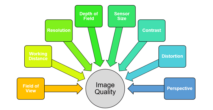
Each of these variables can be seen as levers that affect the overall image quality of your machine vision system, and each will need to be pushed or pulled depending on your machine vision application in order to choose the right components for your system.
Field of View (FoV)
This is the most basic parameter you will come up against when putting a system together and refers to the actual area that you want to see. It may be easier to think about field of view as the ‘frame’ that the camera will capture.
In order to know what field of view is right for you, it’s best to start by thinking about the object you are trying to capture. The bigger the object you are capturing, the larger the field of view you will need.
For example, imagine you want to capture a very large object that has three areas of interest set far apart from each other.
One option would be to try to implement a field of view wide enough to see all three areas with one camera, which could result in a lower level of detail. To combat this, you would need a lens and camera with a high enough resolution to retain the level of detail needed for your application.
Alternatively, you could use three separate cameras, each with their own smaller, and thus more precise, fields of view. The benefit of this approach is that the camera and lens will most likely gain more capable results due to a higher level of detail in the given area to analyse. The downside is using three systems, which will be more expensive and take more time to set up.
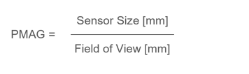
In order to establish the minimum resolvable detail on an object, the ratio of the field of view to the sensor size will need to be calculated. This is known as the Primary Magnification (PMAG) of the system, and can be worked out using the below formula:
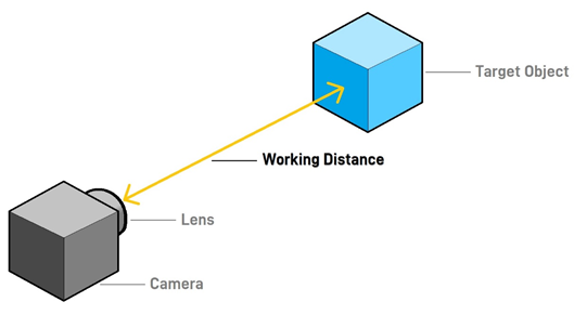
Working Distance (WD)
Working Distance is the distance from the nearest point of the target object to the front face of the lens. This is not to be confused with Total Track (TT) which refers to the distance from the object to the back end of your vision system.
While Working Distance is not inherently a constraint, it can be highly important to get right in many machine vision applications, and extreme working distances (both short and long) can have knock-on impacts on the other key parameters in play.
For example, if a vision system is to be installed in harsh conditions, such as extreme temperatures, dust and dirt, or corrosive substances, a longer working distance would be desirable in order to protect the system. The goal here is to take the camera and lens further away from these harsh elements, meaning a longer working distance. This of course means you will need to consider field of view in relation to magnification to frame the object as clearly as possible.
On the other hand, many machine vision applications take place in claustrophobic industrial environments with limited space, and so naturally a much shorter working distance will need to be utilised. As your working distances shrink, compromises with lighting and resolution start to take effect and the costs can increase dramatically in order for your optical system to perform as desired.
A good starting point is to place your camera 2-5x away from the object relative to its size. This will allow for the desirable flexibility and space to have a reasonably designed system that can execute the optical performances needed for your machine vision application.
Sensor Resolution
This term is used a lot and you may well be familiar with it. Resolution in simple terms is defined as the minimum resolvable detail captured by a camera and lens working in tandem. A camera and a lens will each have their respective native resolutions.
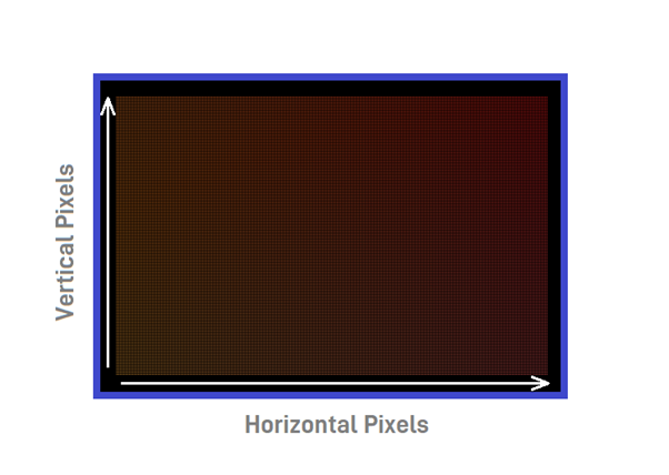
A camera’s resolution comes down to the sensor it employs and is a straightforward calculation. Measured in megapixels, sensor resolution is number of horizontal pixels multiplied by the number of vertical pixels. For example, the Sony IMX296 sensor is 1440p x 1080p = 1,555,200 pixels. This is rounded to 1.6 megapixels (MP).
Sensor Resolution = Horizontal Pixels x Vertical Pixels
Helping You Make the Right Vision Decision
Stay tuned to this series of blogs as we continue to put the spotlight on optics, exploring the remaining fundamental parameters, and later taking a look at aberrations, distortion, and an ultimate guide to choosing the right lens.
Be sure to check our Lenses and Cameras pages for the best machine vision products on the market from industry leading brands such as Kowa, VST, Computar, Tamron, and Theia.

